Motorized ball valve wiring diagram
- Share
- Issue Time
- Nov 23,2023
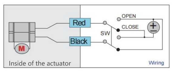
1. Connects red wire to positive pole, black wire to negative pole, the electric ball valve opens.
2. Reverse polarity, the eletric ball valve closes.
※ Once in position, there will be no power consumption.
※ In case of power loss, valve will remain in its current state.
※ Voltage of power supply for option:5V DC/12V DC/9-35V DC
※ A DPDT switch is suggested for a simple set up.

1. Connects red wire to positive pole, black wire to negative pole, the ball valve opens.
2. Connects green wire to positive pole, black wire to negative pole, the ball valve closes.
※ Once in position, there will be no power consumption.
※ In case of power loss, valve will remain in its current state.
※ Voltage of power supply for option:5V DC/9-35V DC/220V AC
※ A SPDT switch is suggested for a simple set up.
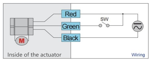
1. Connects red wire and green wire to positive pole, black wire to negative pole, the ball valve opens.
2. Disconnects green wire, the ball valve closes.
※ Once in position, there will be no power consumption.
※ In case of power loss, valve will remain in its current state.
※ Voltage of power supply for option:5V DC/9-24V ADC/220V AC
※ A on/off switch can be installed in line with green wire for a simple set up.
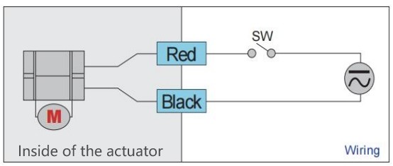
1. Connects red wire to positive pole, black wire to negative pole, the ball valve opens (the ball valve is normally closed by default).
2. Disconnect either wire (the circuit is open), there is no power supply to the ball valve, the ball valve closes.
※ Once in position, there is a nominal power consumption to keep the capacitor charged.
※ In case of power loss, valve will return to its normal position, which by default is normally closed valve. If normally open ball valve is needed, please let us know when place an order.
※ Voltage of power supply for option:5V DC/9-24V ADC/110-230V AC
※ A on/off switch can be installed in line with red wire for a simple set up.

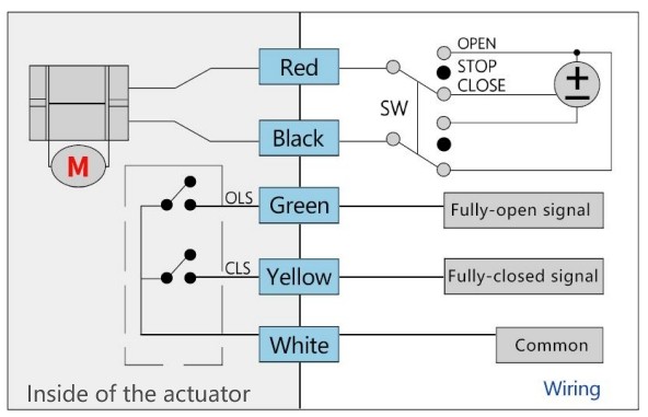
1. There should be 2 power supply, one for electric ball valve actuator - red wire to positive pole, black wire to negative pole; another one for customer’s position indication devices - the green wire outputting fully-open signal connects to one device, the yellow wire outputting fully-closed signal connects to another device, and the devices both should be connected to the positive pole of the power supply, and the white wire of the electric ball valve actuator connects to negative pole of the power supply, there conforms a closed circuit. The valve opens, the open position indication device receives the fully-open signal, will light up if lights are used as position indication devices.
2. Reverse polarity, the ball valve closes, the close position indication device receives the fully-closed signal, will light up if lights are used as position indication devices.
※ Once in position, there will be no power consumption for electric ball valve, nomial power consumption for position indication devices.
※ In case of power loss, valve will remain in its current state.
※ Voltage of power supply for option:5V DC/12V DC/24V DC
※ A DPDT switch is suggested for a simple set up.